Introduction
This page is about the origins of the steam engines of the early 18th century. Various views on this are examined on the A problem in the history of science and technology page. The currently prevailing view is that the development of the Newcomen engine, the first successful steam engine, was enabled by scholarly investigators in the sciences: First came the science, then came the technology
. This view is supported by arguments about how the principles and concepts formulated by previous scientific work made a vital contribution to the development. Some of the arguments assert that the development would have been impossible without the input from science. This page provides an account of how it could take place without that input.
There are many accounts of the history of the steam engine. The conventional approach presents descriptions of miscellaneous experiments that relate to getting power from steam, or relate to the eventual arrangement of the engine. These descriptions are adapted from publications that report advances in the history of science. They are followed by a description of the basic arrangement of the working engine, explained in terms of these advances. The reader naturally has the impression that the developers of the engine applied these advances in their work. The approach on this page is instead to present the problem the developers were addressing, and the technical issues and arrangements familiar to them. This approach is intended to reveal whether the developers could have completed their work with just the material, understandings and experiences available from their working lives.
One area where the scholarly investigators and their associates did have an impact on technical activity was in the development of a rival steam powered pump with a very different layout from the Newcomen engine. An account of this device, its simplicity, elegance and subsequent evolution in the face of failure, is also given below.
The problem: Raising water
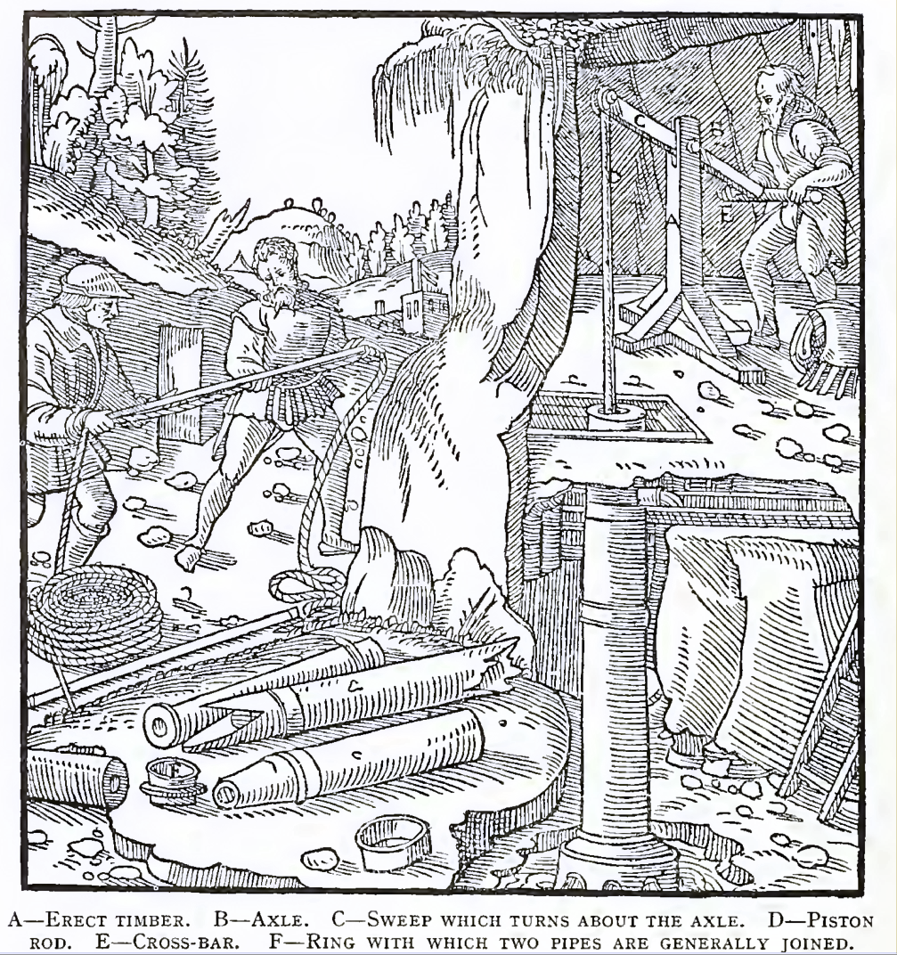
Raising water is an ancient art. Pots and buckets serve well, but it is heavy work; the earliest technical developments lighten the load by enabling the worker to remain in one place while lifting the container, and then by balancing the weight of the container. More advanced developments use multiple containers on a chain, which extend the height of lift from a single source of power and facilitate the use of non human power as well as balancing the containers. The force pump and its pipework are a radical development, where only the water is raised. The pump requires complex and accurate work in a material of high quality, to sustain the pressure, its environment and wear, while keeping leakage and friction low. The pipework has to be extensive and reliable as well as sustaining pressure and its environment. But if these technical requirements can be met, the pumping system is economical, efficient, and relatively compact.
These systems have been used and understood for two thousand years or more, with wood as the main structural material. A more recent development is the suction pump of the fifteenth and sixteenth centuries: "The suction pump soon became so useful that by 1550 it was firmly established as a part of mining technology" (ShapiroThe Origin of the Suction Pump, Sheldon Shapiro, Technology and Culture, Vol. 5, No. 4 (Autumn, 1964), pp. 566-574 p574). Large pumps were made in wood, and small ones apparently in metal. By the end of the sixteenth century the pump was effective enough to show a limit to the head of water that could be raised by suction, as about 9m of water. This prompted the development of atmospheric science. The continuing development of metal extraction, alloying and working enabled the regular production of pumps of diameters up to 170mm in brass by the end of the seventeenth century. The rising pipes were still made from hollowed out trees.
Pumping systems provided the immediate context for the development of steam power, but other technical capabilities were also significant. Brewing employed copper boilers of over 4000 litres capacity. Copper pipework and brass fittings, fixed with lead/tin solder were available. Water and wind power had demonstrated the value of a mechanical power source, gave experience of how to harness and transform it, and gave insight into the technical problems involved in doing so.
Of the many attempts to get power by using fire to generate steam, there are two which were of practical consequence, and these are examined in detail below. They were undertaken independently at about the same time. Thomas Savery took a technically less demanding approach, and obtained a patent, but his design could not be made into a reliable and useful machine. Thomas Newcomen spent 20 years developing an engine of which examples were installed at over 100 sites in the 20 years following its appearance. The development of the Newcomen engine is examined here first. This engine has been widely studied, and was the subject of contemporary and modern investigations, and its performance is relatively well documented. The Savery device is well known, but is less consequential, and how it performed is less clear. Although Savery's design did not work as intended, it was rearranged and modified over the following 60 years with some success. The account of this is given second.
The fire engine
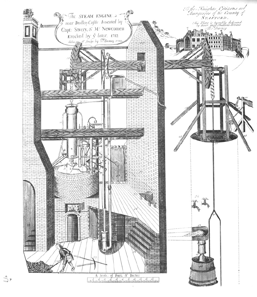
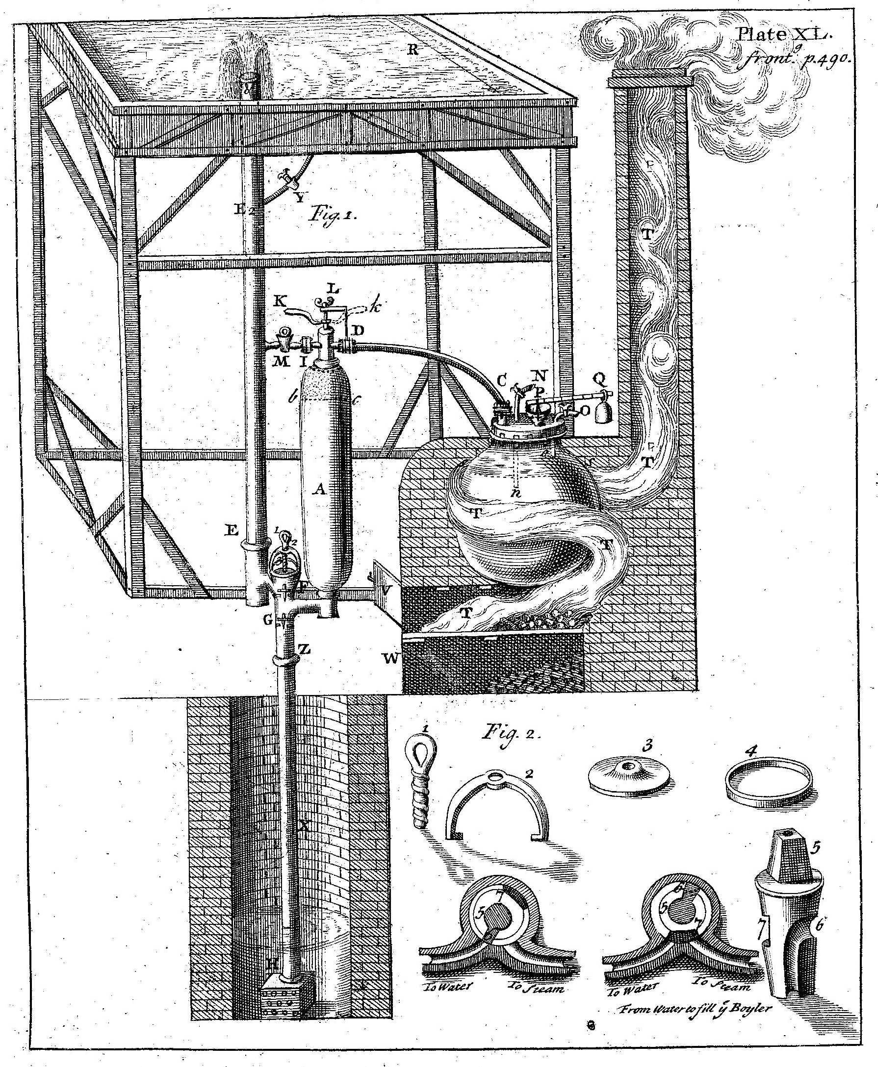
"In the whole history of technology it would be difficult to find a greater single advance than this and certainly not one more pregnant with significance for all humanity" (Lionel RoltThe steam engine of Thomas Newcomen, L.T.C. Rolt & J.S. Allen, Moorland, Buxton, 1977 p38). The engraving shows an impressive machine. It is not quite as impressive as it appears from the size of the man in the foreground, who is drawn out of perspective, but the scale at the foot of the picture is about right for the machinery: the cylinder (4) was nearly eight feet tall. The engine was developed by Thomas Newcomen, an ironmonger and John Calley, a plumber, of Dartmouth, and employed to pump water from a deep coal mine at Dudley Castle. There is a replica engine at a museum near the original site, and there is an account of how that was built here. This is a substantial and costly machine: its 21 inch diameter brass cylinder exerted over 1.5 tonnes force through a 1.5m stroke every five seconds, and it was largely automatic in operation.
There have been questions ever since about how an ironmonger and a plumber could achieve the advance of harnessing steam power, an objective which defeated the finest minds of the age. One answer is their persistence and determination: recent research (Greener) suggests that they started the work around 1689, experimented with an alternative device around 1700, and successfully commissioned their first engine at the Great Work tin mine in Cornwall in 1705. That engine is thought to be of similar size to the 1712 design, but not as fully automated. They built another engine in 1706 at the Balcoath tin mine, and may have relocated it to Wheal an Vor in 1709.
There was plenty of motivation to solve the problem of mine drainage, since the cost of horse or human powered engines for raising water was prohibitive for deep mines. There were also opportunities: the bob gin, a water powered beam pumping engine which used reciprocating pumps, was more widely used thanks to improvements in pump technology which made them more efficient than continuous chain systems. A piston could be simply coupled to a bob gin without the extra machinery needed to make it work the old continuous system. There was also a temporary reduction in the tax on shipping coal to the tin mines that made the fire engine more economical to fuel.
There were even more opportunities in the coal fields. In 1560 the annual British production of coal was about 210,000 tonnes; in 1690 it had risen to 2,982,000 tonnes (Robert Merton Science, technology & society in
seventeenth century England, Robert K. Merton, Harvester Press, 1978 p139). During this period 75% of all the patents taken out in England were connected to the coal industry. The increased production and use of coal as a fuel meant both that the fuel cost of generating steam was reduced, and that the demand for pumping out deep mines increased, and that the fuel was particularly low cost at the point where pumping was required. Even today, when transport costs are much lower, coal costs about seven times less at the mine than it does when delivered to a distant site.
This background supplies answers as to why the fire engine was developed there and then, but not as to how it was possible, nor as to why it took the successful form that it did. To try to answer the first question, let us look at the parts of the engine and pumping system.
The boiler
The technology for heating large volumes of liquid was well established: copper kettles of similar capacity to the boiler in the Fire Engine (about 4000 litres) had been in use in brewing for 200 years (UngerThe history of brewing in Holland, 900-1900 : Economy, technology, and the state, BRILL, 2001 p109).
The pumping system
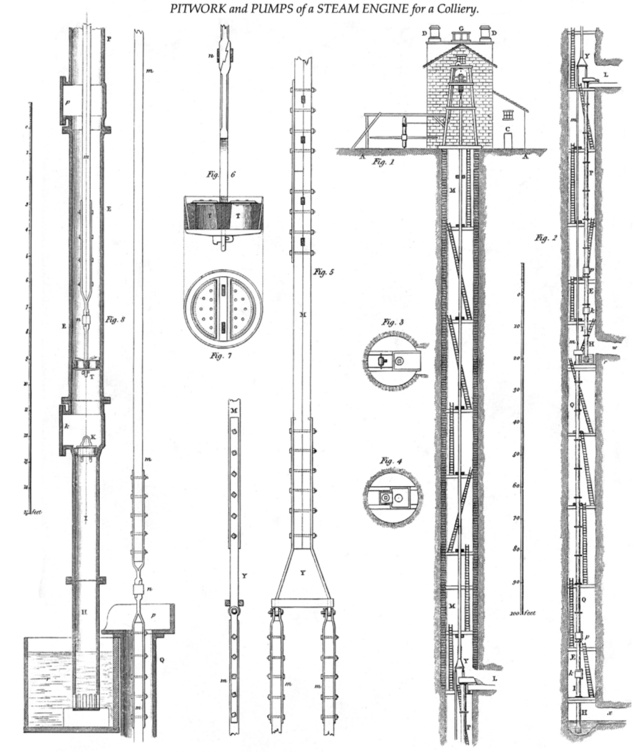
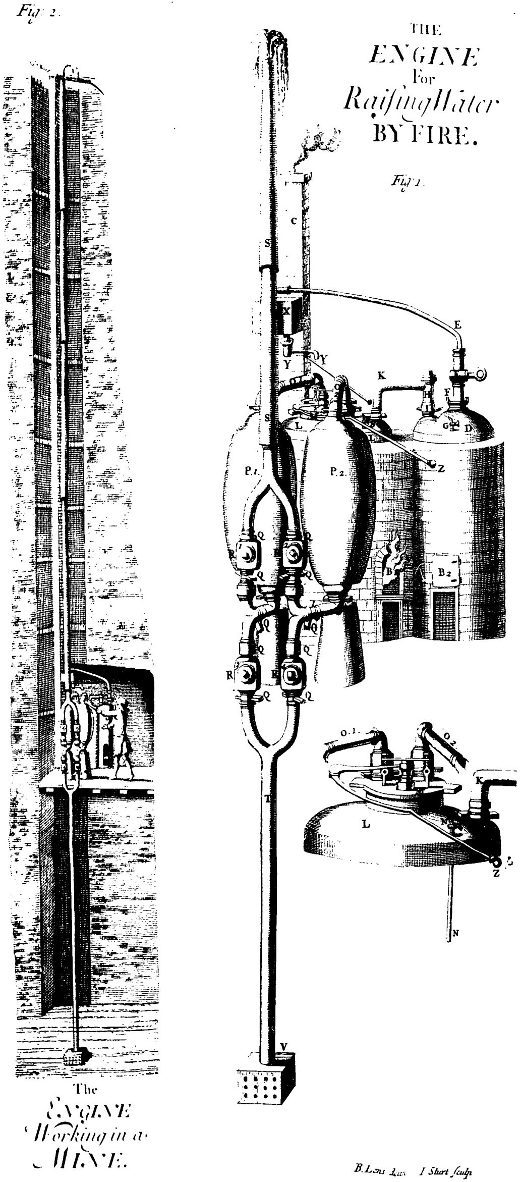
The fire engine is impressive but it is only the tip of the iceberg: the pumping system for a mine 110m deep is illustrated in the picture. It makes use of an adit (marked L), an underground conduit leading to an outlet on lower land, so the water does not have to be raised all the way to the surface at the pump head, but only has to be raised by about 60m and discharged into the adit. Even this lift is too large to be pumped in a single stage: the equipment cannot withstand the pressure of a 60m head of water. The lift has to be split into two separate stages, with separate pumps. Each pump (marked E) draws water up by suction from a sump or cistern below, and forces it upwards at a safe positive pressure to discharge at 24m above.
Newcomen and Calley worked closely with the engineers in their mining community, so they were informed about the supply and maintenance of piston and cylinder pumps, valves, pipework and connectors. They knew about the limitation of suction, that it could not draw water reliably by more than 8.5 metres, and the problem that an excessive forcing pressure would burst open pipes or vessels made to contain it. They could calculate the force needed to raise the water, and the force that might be exerted on a piston by suction.
The ideas
The facts that boiling water to generate steam produced high pressure, and that the condensation of steam produced suction were common knowledge (Clark An elementary treatise on steam and the steam-engine: stationary and portable, Clark, D. K, London: Lockwood p14, Burn The steam engine: its history and mechanism, being descriptions and illustrations of the stationary, locomotive, and marine engine, Burn, Robert Scott. London : Ward, Lock and Tyler, [1875?] p25). The idea of using the power of steam to do useful work has been around since before 100CE; it was taken up in the seventeenth century by many people. Of the attempts on record, most of them tried to use the pressure of steam directly on to water in a closed container to force the water upwards.
So we can see that the necessary ingredients and experience are available to Newcomen and his co workers to fabricate an engine of the same type as the Dudley Castle engine. Next we look at why it took the form that it did.
Putting it all together
There were two key choices that the the developers of the engine made: (i) to use suction from condensation instead of positive pressure, and (ii) to use a piston and cylinder to convert the pressure into a force instead of directly applying it to the water.
The reason for avoiding positive pressure is that the boiler has to withstand it, and if it fails the results are fatal. A plumber is well aware that his installation must be restricted to a safe head of water. A pipe joint has to be bigger and more robust to take a higher pressure. The brewer's kettle has only to withstand the weight of water it contains, so any attempt at high pressure steam would be a new and risky venture. Contemporary correspondence (J S Allen) shows that Newcomen was respected for his good and honest conduct, and that the engine was regarded as "the cheapest and safest way of keeping the colliery dry". These are sufficient reason to explain his avoidance of steam at elevated pressure. The soundness of the decision has been reinforced by the disastrous failures of rival positive pressure steam devices.
The only alternative to elevated pressure is to use condensation to reduce pressure and deliver suction. Since the depth of the pumping is far beyond the head achievable by suction, direct application to the water would require multiple engines in stages, neither safe nor economical. The pumping system was familiar technology, so if a machine could be devised to deliver the necessary force and stroke, a solution was within reach. Newcomen's piston and cylinder convert pressure into force; the same components in the underground pumps do the reverse. Their experience of pumps could be brought to bear on creating the new machine. These are good reasons for Newcomen to attempt a piston and cylinder arrangement, but much work remained to be done. The next problem they faced was to generate enough force to deliver the pumping action by lifting the pump rods and the water in the pipes. Brass pump cylinders were made at up to seven inches in diameter; the weight of the water alone on a 45m lift would require the suction cylinder to be over five times the area of the pump cylinder, far larger than anything available then.
It is generally supposed that Newcomen's early attempts at constructing an engine were on a smaller scale than the working machines on record. The components of a pump could be adapted to provide the steam cylinder and piston for a model engine. So a model could be undertaken, but did they have the equipment and understanding to progress it to the point of positive results?
First, a basic arrangement was needed: The pump rod has to be driven up, but it will go down again under its own weight. The simplest way to work the cylinder is to supply steam through a valve to the closed end of the cylinder so that the piston moves out as the cylinder fills with steam, then shut the valve and allow the steam to cool and condense, which sucks the piston in. The force from the piston has to be applied to pull the pump rod up, but to do that directly produces an unfeasible layout. The arrangement of a lever to make the direction of the force to operate a pump more convenient is familiar, and produces a tidy layout with the closed end of the cylinder fixed to the building structure.
The problems they faced next can be appreciated by looking at a modern account of the construction of a one third scale model Newcomen engine, with a seven inch bore cylinder. (Hill p67). Starting from cold, if the cylinder is filled with steam and then the steam valve is closed, the model executes a stroke. The steam condenses quickly and the piston is drawn in, but air can be heard leaking past the piston seal. The solution they chose, familiar from priming a suction pump, was to add a little water above the piston to reduce the volume of air leaking in. The engine starting from cold executes three or four strokes just by opening and shutting the steam valve, but then it slows and finally halts because the cylinder has heated up and the steam does not condense any more. To solve that problem they improvised some cooling of the cylinder with water run over its outside surface. That expedient extended the run time, but eventually condensate accumulated in the cylinder: they fitted a drain valve to remove it. More careful arrangement for cooling the cylinder just when condensation is needed produces extended cycling, and the vision of a usable engine is in sight. But... the engine operated too slowly: the time taken for cooling and condensation is so long that the pump delivery rate does not justify the cost of buying and running the machine. The story is told by a contemporary of how they persisted, trying to cool the cylinder with a water jacket, until one day an accidental leak of water into the cylinder caused such rapid condensation that the descent of the piston damaged the pipework (Triewald Mårten Triewald's short description of the atmospheric engine, Stockholm, 1734 p2). Another problem arises in trying to make the engine more economical: if the steam input is shut off exactly when the piston is at the top, air builds up in the cylinder and the stroke is reduced. To prevent this, an excess of steam is let into the cylinder at each stroke to clear the air.
It is clear that with inventive spirit and determination, as well as technical resources and commercial awareness, they were able to create a working model engine. To go ahead to produce a full size machine capable of sustained operation also required an extension of contemporary technical capabilities. The brass steam cylinder had three times the bore of a pump, and had to be robust, accurate and well finished. The engine house, lever and cylinder mountings had to sustain loads of an unprecedented kind. It is no surprise that more than twenty years of development and two earlier engines preceded the Dudley engine, with its automated valve action and advanced design of water injection valve nozzle (Hill ).
Existing pump systems were driven by water power, if it was available, or horse gin if not. The new engine had to compete with animal power for cost. The engine consumed about 150 kg of coal per hour. At present day prices that would cost about €2.5 at the mine, or as much as seven times that delivered to a distant site. For comparison, the cost of using electric power to pump that much water today would be about €1 per hour, and the cost of horses about €8 per hour. In 1752 the cost of using a Fire Engine was estimated as 40% less than using horses (TunzelmannSteam power and British industrialization to 1860 G N Von Tunzelmann, Oxford : Clarendon Press, 1978 p120). The demand for the new engines was driven by the operation of deep mines in areas where coal was cheap.
The proof of the value of this work is that in the 21 years after its introduction over 100 engines of this type were built under patent, with cylinders exerting up to three times as much force as the Dudley Castle engine. At Coalbrookdale, iron cylinders were developed as an alternative to the expensive brass ones. The change was not just technical, it was economic and industrial.
These engines were not applied to the general task of supplying power for the wheels of industry, for which water was to remain dominant. They were also expensive to run if not part of a coal mining operation, and the smaller engines were even less fuel efficient. The problem of turning a wheel was that it required a more controlled and uniform stroke than the early engines gave. The wider application of steam power was made possible by the separate condenser and the steam jacketed cylinder developed for the fire engine by James Watt. And the rest is history...
The engine for raising water by fire
Thomas Savery came from a prosperous merchant family in Devon, but little is known about his early career apart from some evidence of a military engineering connection. He petitioned for patents for a glass polishing machine and a capstan powered boat in 1694 which, despite his publishing a 22 page pamphlet refuting criticisms of it, was not taken up by the navy. In 1698 he was granted a royal patent for An Engine to Raise Water by Fire, which had been demonstrated to the king. In 1699 the patent cover was extended by act of Parliament from 14 years to 35 years.
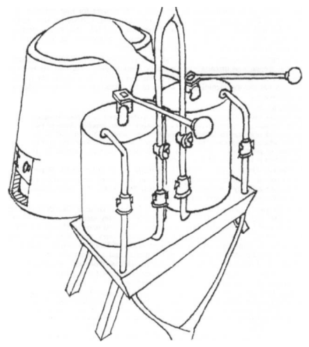
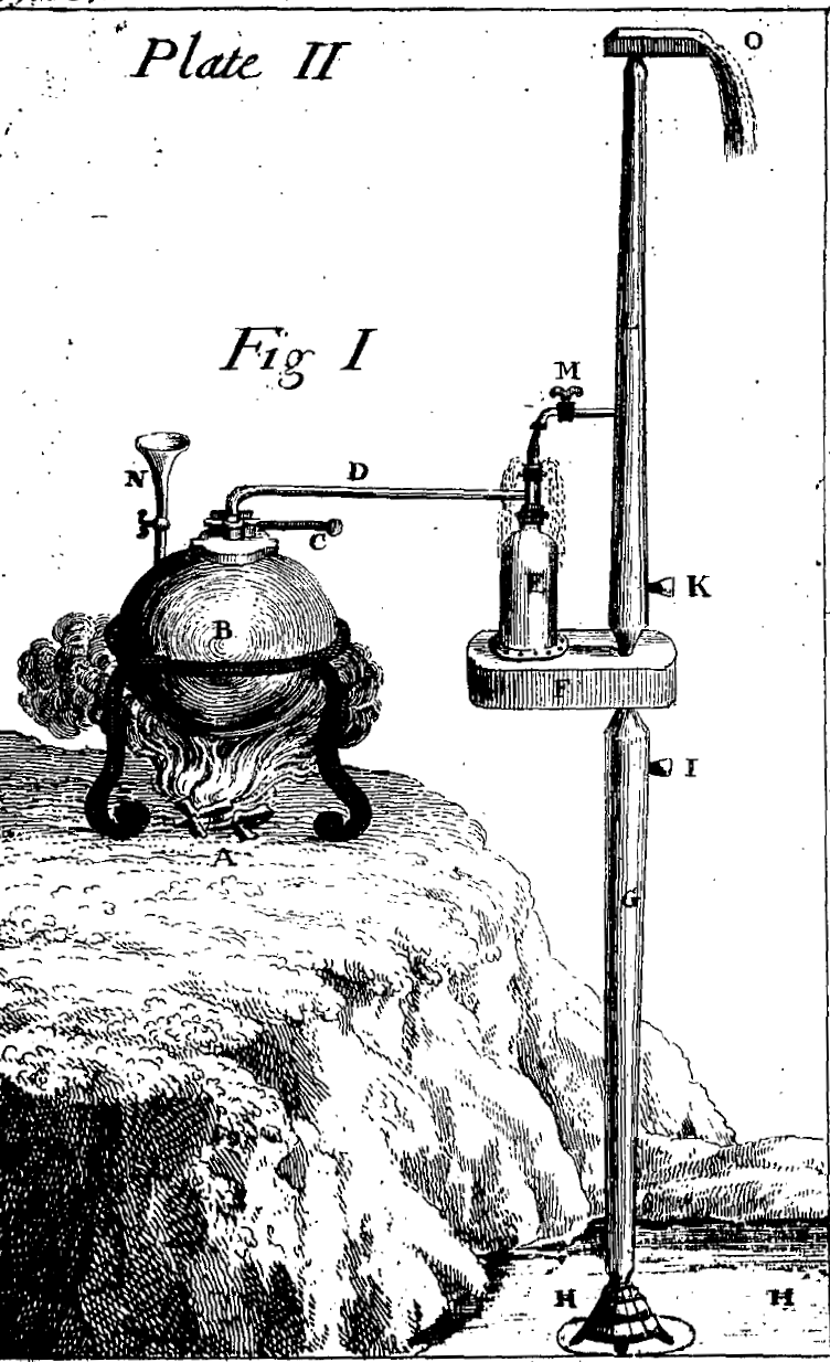
moddle engineas presented to the Royal Society of London
Savery developed a neat and economical arrangement of boiler, non return valves and twin receivers, which used suction from condensation to lift water into one receiver, then positive steam pressure to force it up a further delivery pipe, refilling that receiver with steam, ready for another cycle. The other receiver operated in anti phase, giving extra flow and almost continuous delivery. A steam valve on each receiver was operated manually, opened for steam inlet and closed for condensation. Savery successfully demonstrated a moddle to the Royal Society in 1699, depicted at left. In 1700 his Scottish patent application claims an improved device capable of lifting "20 tuns per hour" through 84ft. This performance is well in excess of anything recorded subsequently by developers using similar arrangements, which are examined below. In 1702 Savery was advertising twice weekly demonstrations of a “small engine” at his London workshop. His booklet The Miner's Friend The Miner's friend, An Engine to Raise Water by Fire, Savery, Thomas, 1650?-1715 London, S. Crouch, 1702. Reprinted, 1827. of 1702 gives a glossy presentation of the device, with provision for water cooling to speed the condensation, giving the impression that several examples were at work, but without detail of capacities or capabilities. The boiler, receivers and connecting pipework were in copper; appropriate valves were used to control steam and cooling water by hand; no provision was made for estimating, limiting or regulating steam pressure.
The plan eloquently advocated in "The Miner's Friend" was to replace the pump in the mine pumping system with the new device, with multiple devices for deep mines, see figure at right. This plan never came to pass. The first attempt at an installation at Wednesbury in 1705 failed on trial when the device exploded. It was not used in any attempts at mine drainage after that. Another example of the Savery twin receiver arrangement was installed at York buildings in London for water supply, but could not be made to work reliably.
Savery's engine may not have worked, but his long patent cover was put to use. An agreement was reached to work the Newcomen engine under the patent, and Savery's name appears as an inventor on the engraving of the Dudley castle engine. After Savery's death in 1715 the patent became vested in a company, which went on to market the Newcomen engine (Jenkins p119).
Savery did not return to mine drainage, but applied his efforts elsewhere: in 1705 he was appointed a Treasury Commissioner, translated a Dutch Military work, and exhibited his model to the Landgrave of Hesse. In 1706 he was elected an FRS and applied for a patent for double acting bellows. In subsequent years he applied for patents for a floating water mill, a new sort of oven using low grade coal, and an instrument for measuring the ship's way at sea. None of these became working projects. The year before his death he was appointed Surveyor of Water Works at Hampton Court.
Variations on a steam pump
Savery did not achieve his intentions with the miner's friend, but according to Desaguliers p466 ...he did erect several, which rais'd water very well for Gentlemen's Seats;
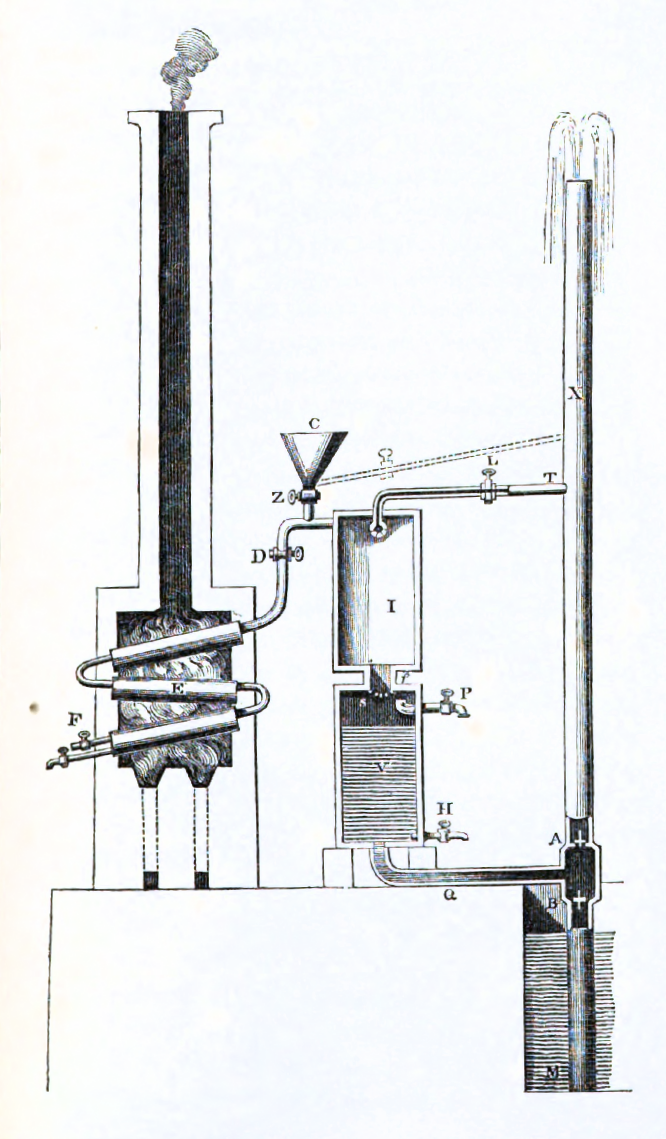
. In New improvements of planting and gardening, both philosophical and practical (1718, p174. Figure at right) Richard Bradley FRS describes a device erected by Savery in 1712 for the gardens at Camden House, Kensington as working well. The twin receiver arrangement described in The Miner's Friend was discarded in favour of a single receiver. The boiler, steam pipe and receiver were made in copper, the suction pipe of 16ft and the force pipe of 42ft made in wood; the receiver was 60 litres the boiler was three times as large, and it ran at four cycles a minute using external water cooling for condensation. Bradley calculates an hourly delivery assuming a full receiver delivered at each cycle, but does not report any measured output. Switzer reports the original version as still working in 1729. A similar device was installed for the Duke of Chandois at Sion Hill.
In A course of experimental philosophy (1744) John Desaguliers FRS gives a detailed description of the construction and operation of a Newcomen engine, followed by: ...an account of some improvements I have made in [Savery's method] and in what cases it is more useful...
. His improvements include using injection cooling in the receiver, as developed for the Newcomen engine, to speed up the cycle time and increase delivery rates. He also adopted the single receiver arrangement, backed up by experiments on models which showed the single receiver delivered larger output than the twin arrangement, due to more rapid cycling. He fitted a safety-valve to the boiler (at PQ in the figure at left).
He reports that he has caused seven of these Fire Engines to be erected
for ornamental gardens, one for Czar Peter. One device, installed in 1717, drew 29 ft and forced 11 ft using one receiver of about 240 litres capacity and a boiler five to six times that size. Another, from about 1720, draws 29ft and forces 24ft and cycles six times a minute, lifting 15 tuns per hour using the equivalent of a parlour fire. He also reports a test comparing a model Newcomen engine having a cylinder about 10 litres capacity which raised 4 tuns/hr against one of his own with a 40 litre receiver which raised 10 tuns/hr, using the same boiler.
These proponents of Savery's method seem infected by his excessive optimism. Bradley states that the suction and forcing could be extended to 28ft and 100ft, without mentioning the drawbacks and dangers of doing so. The second receiver he proposes led in practice to unreliable operation. Desaguliers description of the device lifting 15 tuns per hour being fueled by a parlour fire is not consistent with later findings (FareyA Treatise on the Steam Engine Vol I 1827, John Farey) which indicate a coal consumption ten times that amount, even allowing that a gentleman's seat might have a large parlour. Desaguliers' test comparing his device to a small Newcomen engine has not been critically examined (Friedel Robert D Friedel, A culture of improvement: technology and the Western millennium, Cambridge, MA : MIT Press, 2007 p198, AllenRobert C Allen, The British Industrial Revolution in Global Perspective, Cambridge University Press, 2009, WoottonDavid Wootton, The invention of science : a new history of the scientific revolution, Penguin, 2015). The results do not justify his claim that they show his device to advantage, since his receiver had a capacity of about four times that of the cylinder of the Newcomen engine and used the same boiler. The engine was too small to use the capacity of the boiler, which limited its performance. For a meaningful comparison the cylinder size must match the receiver size, and the pump driven by the Newcomen engine be matched to its lift. Desaguliers reports that a fatal explosion of the receiver was entirely due to the uninstructed and ignorant man working the engine, who hung a plumbers iron on the safety valve to speed his work. His confidence that a properly operated safety-valve is a reliable solution seems excessive in the light of boiler explosions that occurred in other similar installations.
Subsequent developers identified the problem that in a direct pressure device the steam is applied to a water surface which vigorously condenses it. Pressure cannot build up and force the water out of the receiver until the upper layers of water are heated to nearly boiling point. An installation in Paris to supply water to hot baths had some success, but most applications did not need hot water. If this condensation could be reduced the device could run faster and be more fuel efficient.
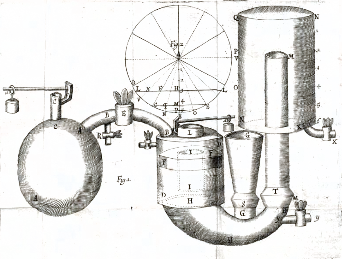
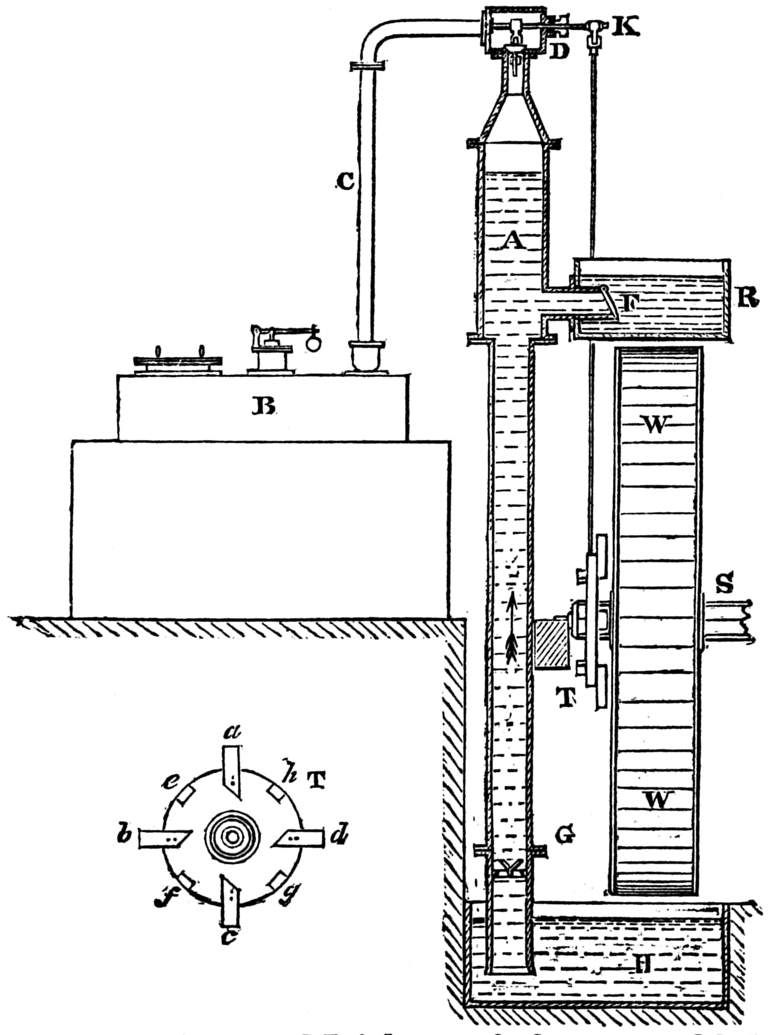
An arrangement which attacked this problem was devised by Denis Papin, who was employed by the Landgrave of Hesse at the time that Savery visited the Landgrave to demonstrate his device. Papin's arrangement used only positive pressure, and placed a floating piston (at FF in the picture) loaded with red hot iron rods between steam and water in the receiver. A model device was constructed, but was dismantled before it could be properly tested. Papin's employment was subsequently terminated after the Landgrave narrowly escaped being one of several fatalities in a boiler explosion.
Another attempt to separate steam and water was made by William Blakey: in 1766 he patented a direct pressure device with injection condensation that had an ancillary air vessel connected above the receiver. The forcing phase admitted steam to the top of the air vessel so that the air, being more dense than steam, acted as a buffer above the water. In the drawing phase the rising water operated a float valve that admitted air above the water to refill the air vessel. In 1776 he patented a version with automated valves, and a form of steam tube boiler. The capacity or fuel consumption of these engines are not given, although Farey reports the air buffer as ineffective; there are reports of its use being terminated by a terrific explosion.
Lasting success was only acheived by abandoning the forcing phase of the cycle and using only the condensation lift phase. The limited lift available was suited to driving a waterwheel. Examples are described by Farey (pp122-5) of installations by Rigley in Manchester and Keir in London where a pump with a 20 ft lift fed a water wheel to provide power for machinery; the wheel was connected to operate the valves automatically. At this time the piston and cylinder engines were not able to provide the smooth continuous motion needed for driving machinery. Tests by Smeaton in 1774 indicated that they had a similar fuel efficiency to Newcomen engines of similar power (two to five hp). Keir claimed a water duty of three times that for a device with an air admission valve which opened just before the steam valve (Hills Power from Steam: A History of the Stationary Steam Engine, R. L. HILLS, CUP, 1989 p48), but Farey reports the Smeaton tests as more reliable, and the air valve as being discontinued without loss of output. Further attempts to develop more efficient direct pressure devices were made up to 1822 (Hills A Steam Chimera: A Review of the History of the Savery Engine, R. L. HILLS, 1986 p38-9), with no success. By this time, more efficient piston and cylinder engines capable of delivering rotary motion were available.
To get a useful outcome from the original Savery pump, most of its elements had to be discarded, and others added: the positive pressure and the second receiver had to go, and injection condensation and a water wheel had to be added. The motivation to try to make it work was that the initial cost was low, and the specialist production and maintenance of the piston and cylinder were avoided.
Review
The success of the Newcomen engine rested on two key technical decisions: the use of condensation instead of steam under pressure, and the transformation of fluid pressure into mechanical force by the use of a piston-cylinder. The result was an engine that was large and technically demanding, but safe, reliable and largely automatic. Savery's device was more elegant and appealed to the sensibilities of the Fellows of the Royal Society who promoted it, but could only persist as an element of a modest but useful device after comprehensive technical transformation.
The decision to avoid positive pressure, despite its advantage of speed and compactness, is particularly important. The use of lead in the boiler and pipework shows a commitment to low pressure. Perhaps a healthy caution was learned from earlier experience with high pressure fluids in mine pumping operations: the limitations of pipework are only found when it fails under pressure. Perhaps news of disaster with a pressurised boiler elsewhere travelled widely, as such news does. Lowther writes in 1715 on the Whitehaven Newcomen engine: 'There is nothing that will do our business so well and be less liable to accidents than that engine'. Newcomen had a strong reputation as an honest and upright man; that might have helped him to realise the uncertainty of success and lethal consequences of failure in using a pressurised boiler, despite its theoretical attractions.
John Desaguliers FRS, on the other hand, was entirely confident that his safety valve could prevent boiler explosions, if only he could get the staff. His confidence in high pressure boilers was unfounded at that time, and even a hundred years later in the United States, forty-two [boiler] explosions killed 273 people between 1825 and 1830
(Friedel
Robert D Friedel, A culture of improvement: technology and the
Western millennium, Cambridge, MA : MIT Press, 2007 p397). The distinguishing feature of the Savery device is that it is a simple adaptation of arrangements developed for the demonstration of pneumatic effects in the laboratory. It was not well founded in the technology it was intended to advance, but was helicoptered in from the world of science.
Conclusions
This page has succeeded in its aim to provide an account of the development of the Newcomen engine that does not involve a contribution from scholarly scientific investigations. This completes the argument from A problem in the history of science and technology, where the issue was raised.
The account is framed in terms of practical arrangements, which provides links into the economic and social environment, and it appears coherent and complete. The Technology and science education page identifies a need for accounts of this type to advance curriculum development in the direction of a balanced presentation of science and technology.
References
- ^ The Origin of the Suction Pump, Sheldon Shapiro, Technology and Culture, Vol. 5, No. 4 (Autumn, 1964), pp. 566-574
- ^ A Treatise on the Steam Engine Vol I 1827, John Farey
- ^ The steam engine of Thomas Newcomen, L.T.C. Rolt & J.S. Allen, Moorland, Buxton, 1977
- ^ Steam power and British industrialization to 1860 G N Von Tunzelmann, Oxford : Clarendon Press, 1978
- ^ Unger, R.W.. history of brewing in Holland, 900-1900 : Economy, technology, and the state, BRILL, 2001
- ^ An elementary treatise on steam and the steam-engine: stationary and portable, Clark, D. K, London: Lockwood
- ^ The steam engine: its history and mechanism, being descriptions and illustrations of the stationary, locomotive, and marine engine, Burn, Robert Scott. London : Ward, Lock and Tyler, [1875?]
- ^ Science, technology & society in seventeenth century England, Robert K. Merton, Harvester Press, 1978
- ^ Mårten Triewald's short description of the atmospheric engine, Stockholm, 1734
- ^ The Miner's friend, An Engine to Raise Water by Fire, Savery, Thomas, 1650?-1715 London, S. Crouch, 1702. Reprinted, 1827.
- ^ A Steam Chimera: A Review of the History of the Savery Engine, R. L. HILLS, 1986
- ^ Power from Steam: A History of the Stationary Steam Engine, R. L. HILLS, CUP, 1989
- ^ Robert D Friedel, A culture of improvement: technology and the Western millennium, Cambridge, MA : MIT Press, 2007
- ^ Robert C Allen, The British Industrial Revolution in Global Perspective, Cambridge University Press, 2009
- ^^ David Wootton, The invention of science : a new history of the scientific revolution, Penguin, 2015

Sources of innovation by S H Joseph is licensed under a Creative Commons Attribution-NonCommercial-ShareAlike 4.0 International License.